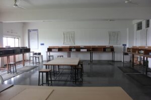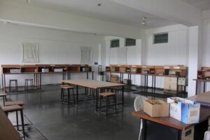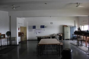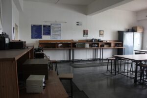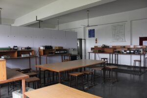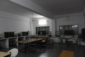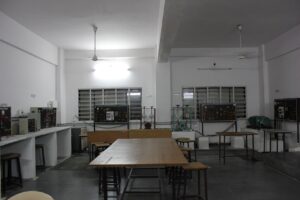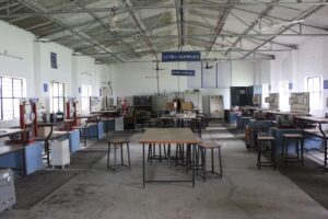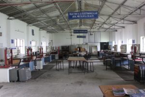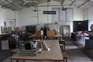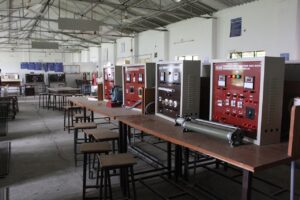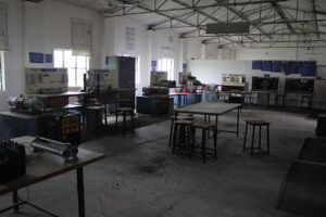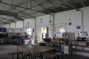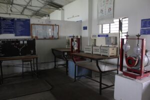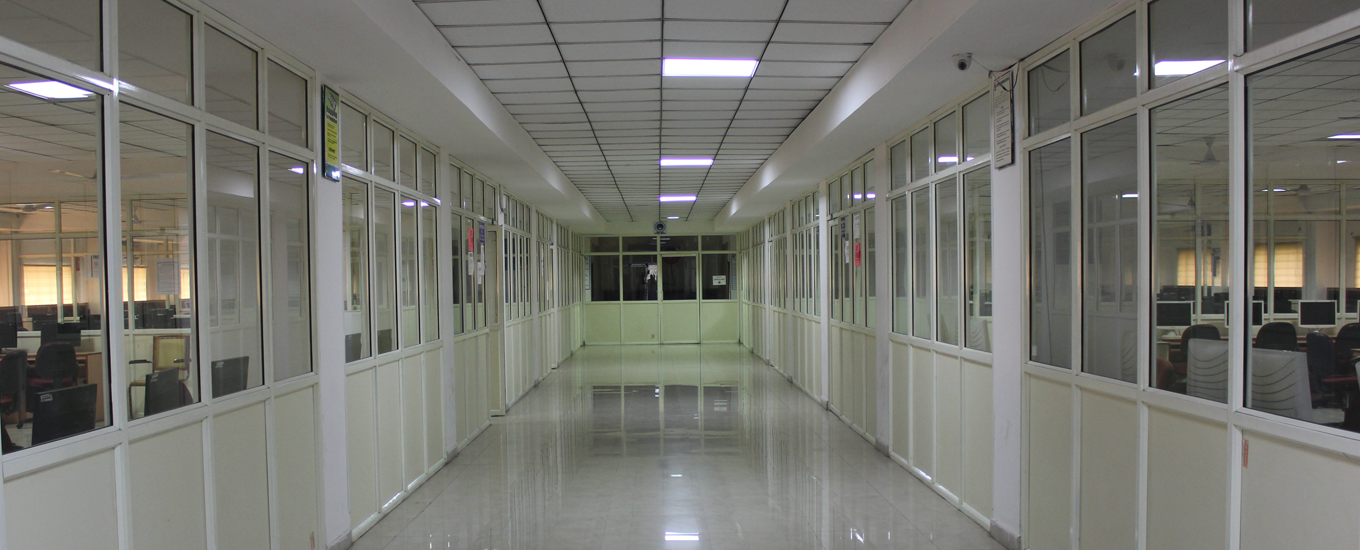
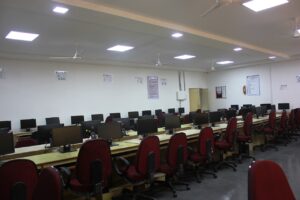
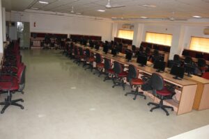
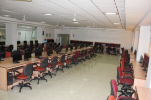
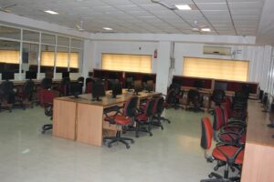
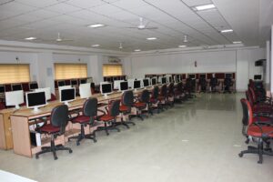
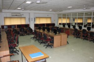
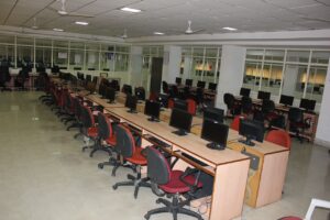
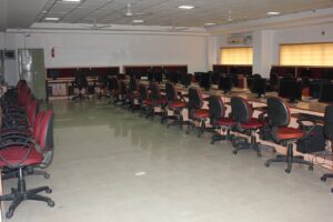
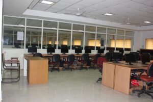
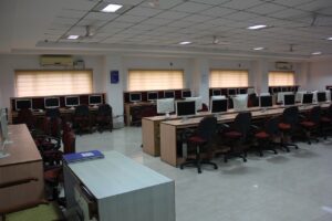
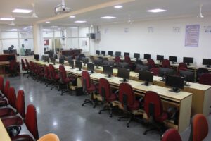
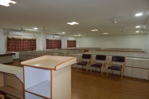
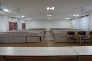
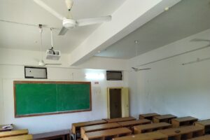
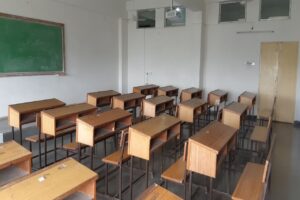
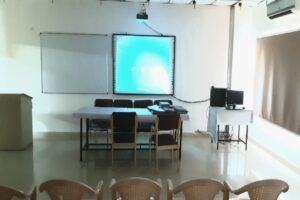
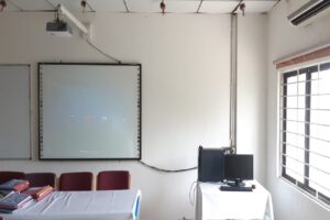
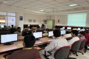
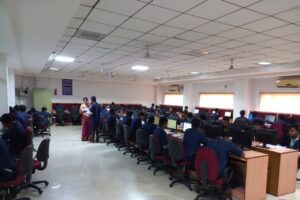
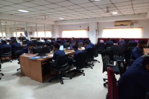
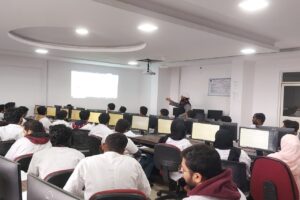
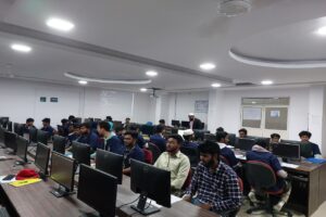
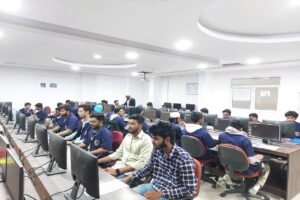
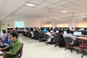
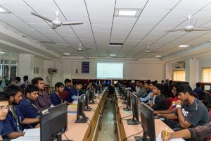
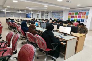
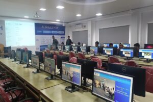
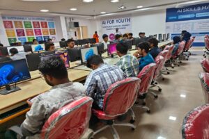
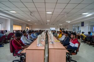
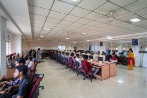
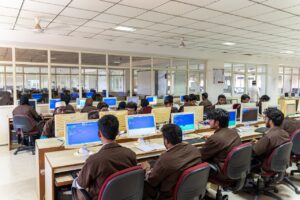
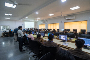
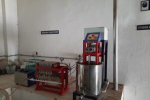
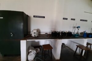
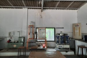
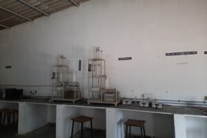
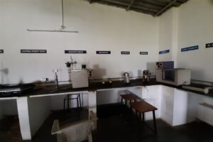
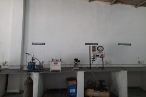
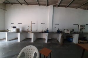
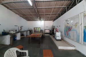
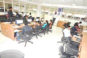
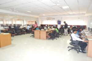
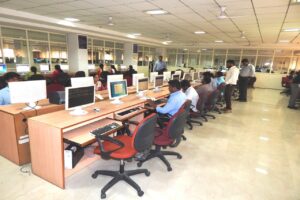
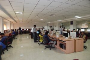
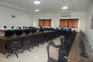
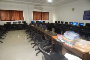
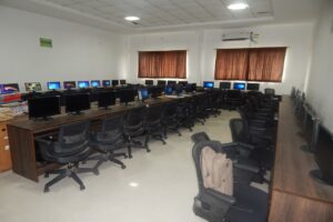
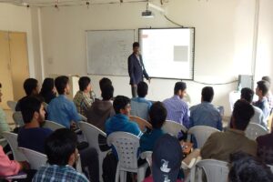
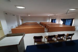
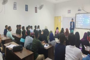
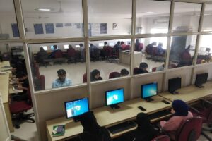
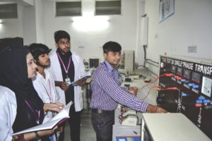
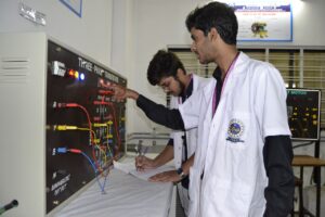
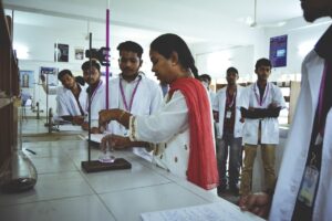
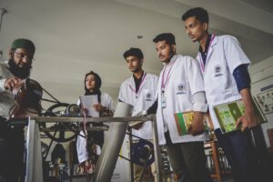
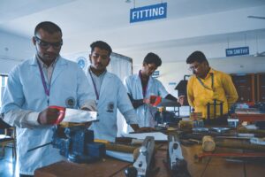
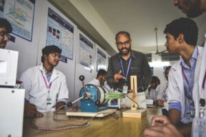
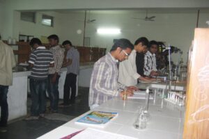
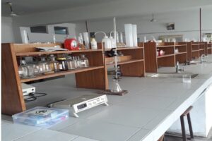
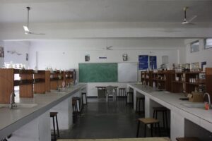
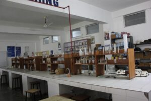
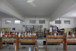
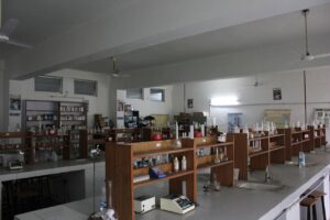
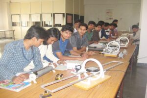
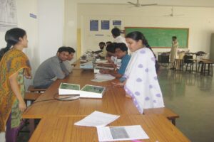
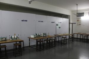
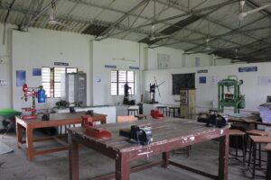
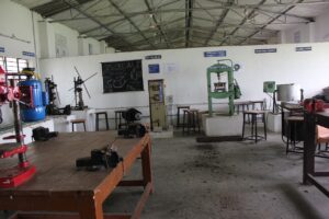
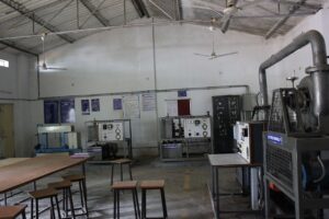
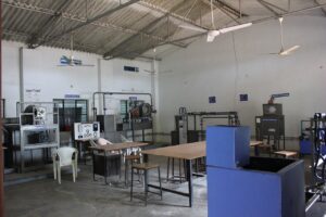
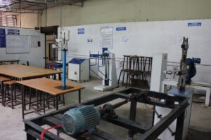
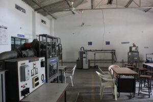
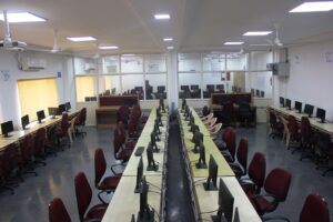
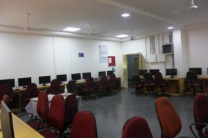
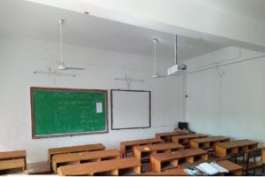
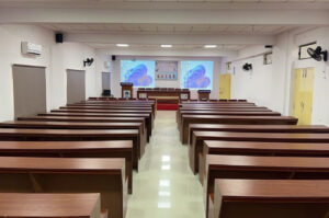
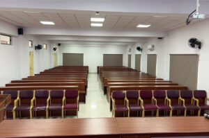
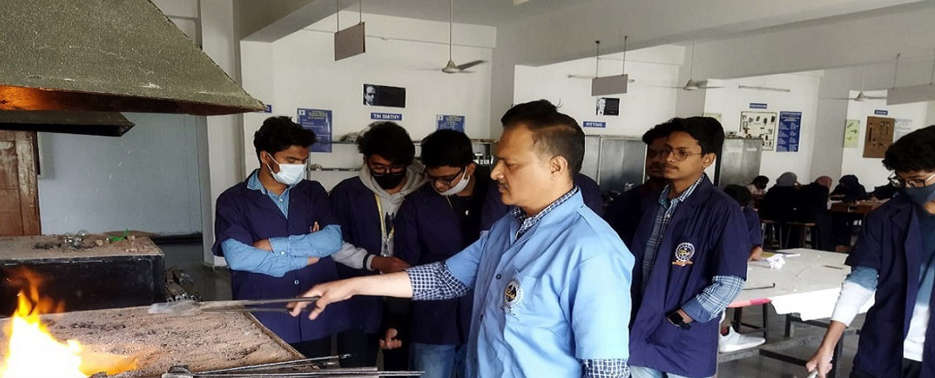
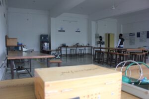
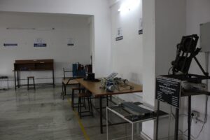
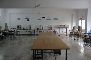
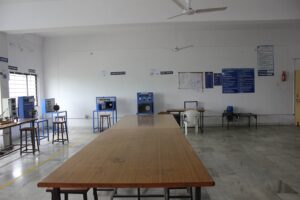
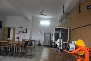
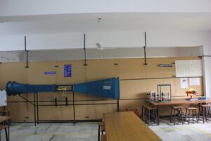
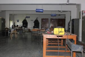
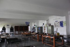
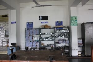
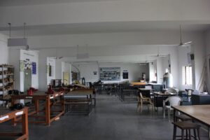
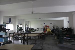
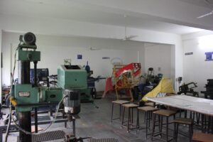
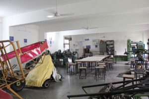
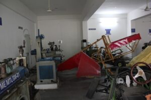
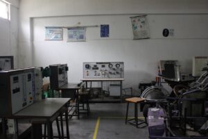
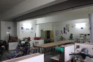
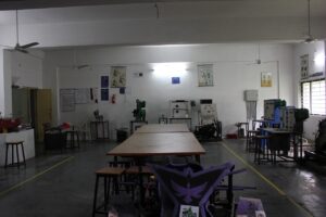
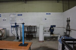
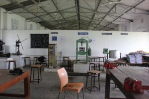
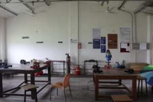
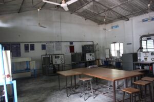
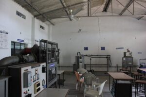
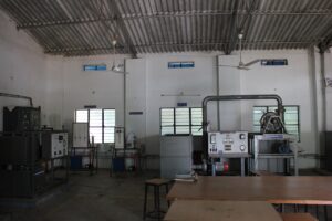
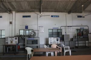
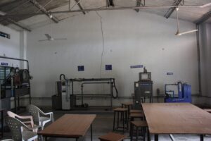
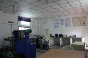
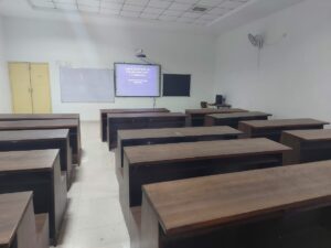
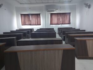
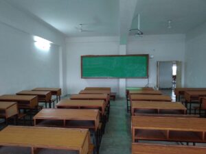
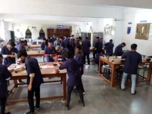
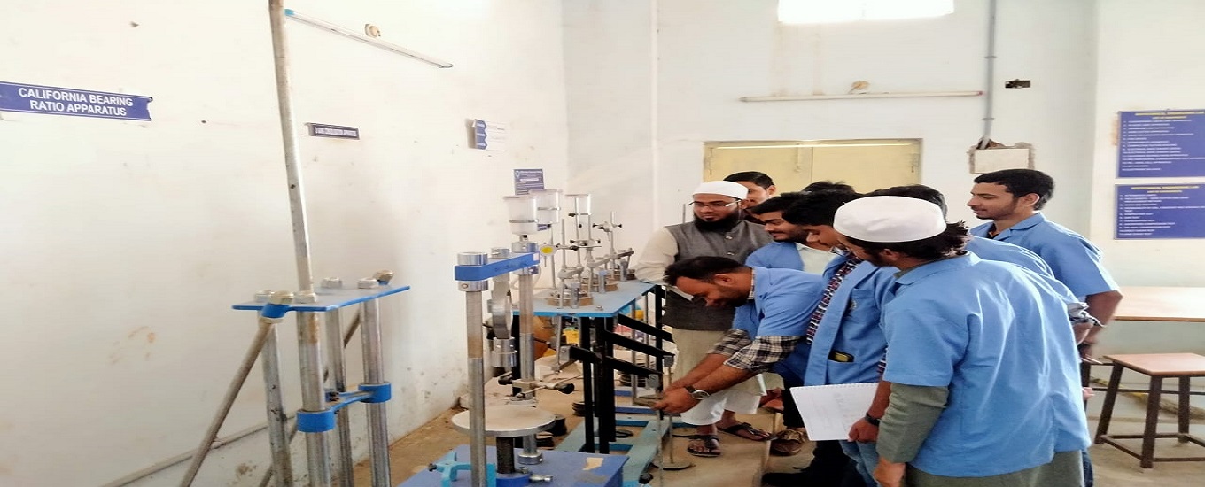
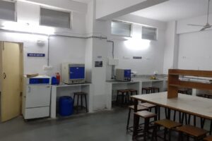
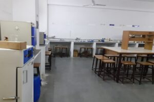
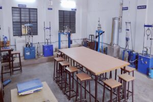
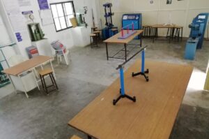
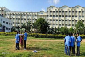
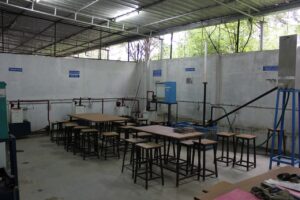
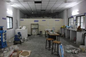
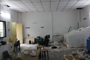
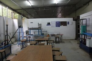
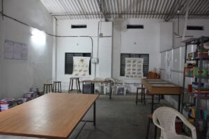
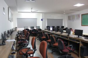
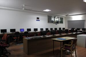
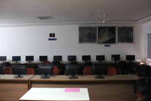
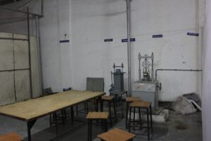
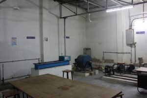
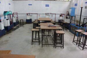
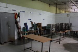
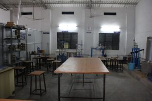
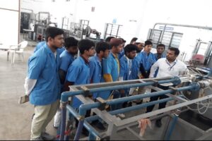
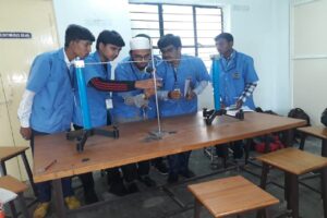
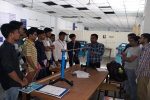
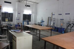
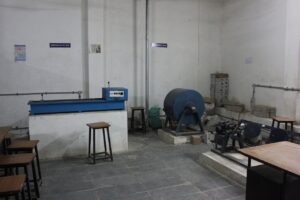
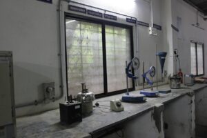
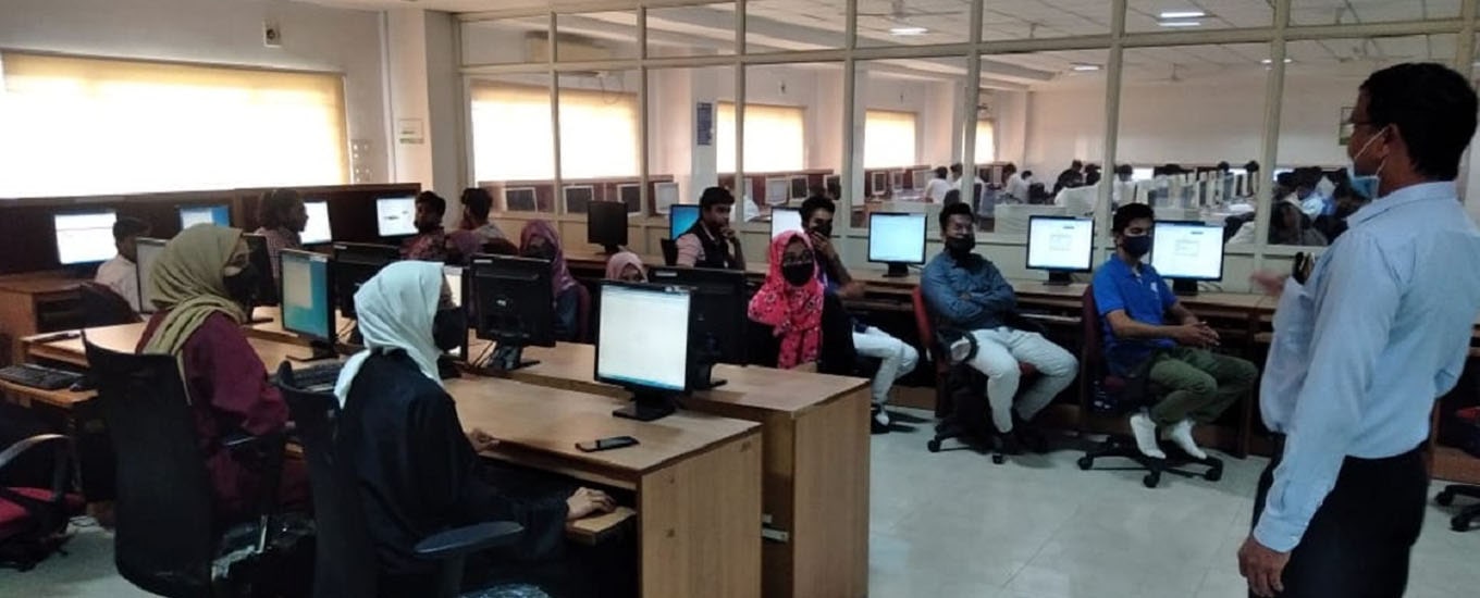
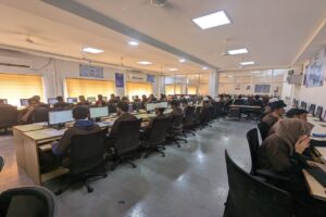
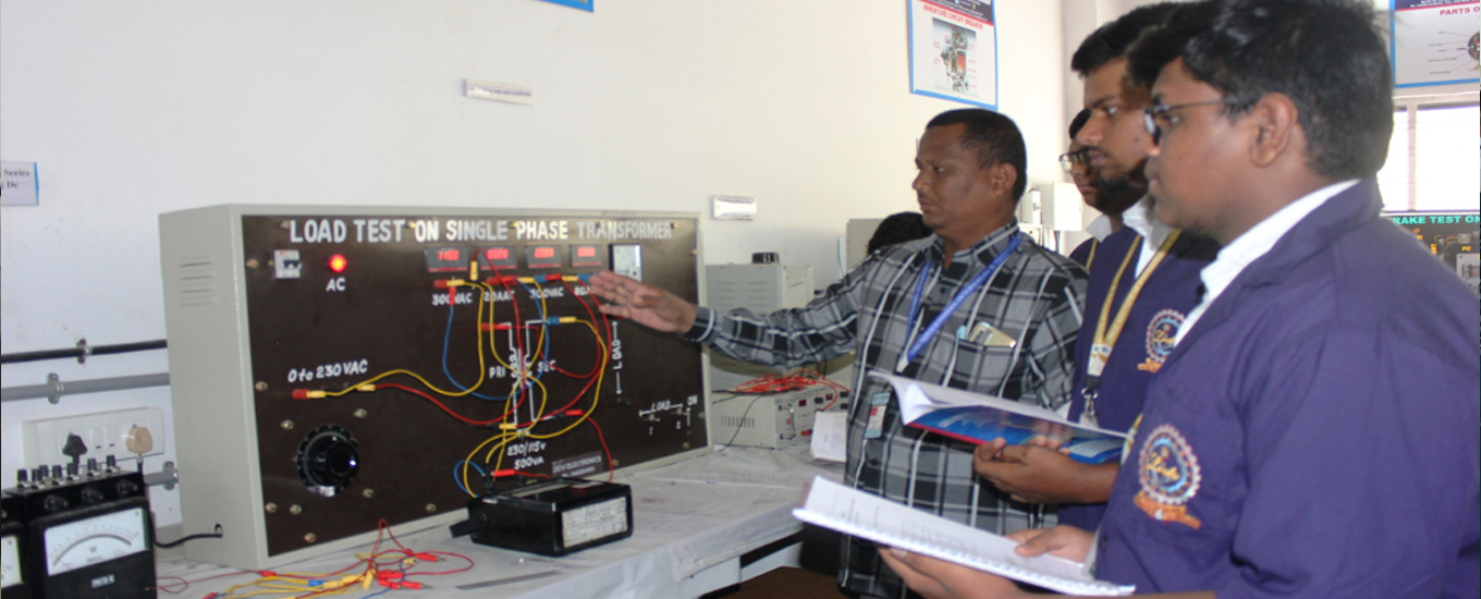
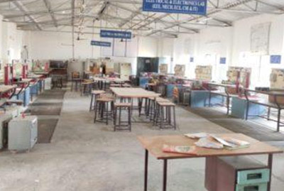
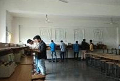
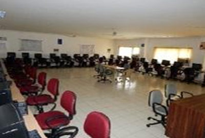
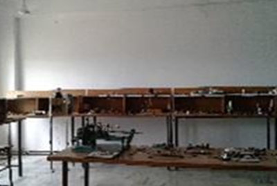
The following are the photos of the labs in the department
EAMCET / PGECET / ECET / ICET Code : LRDS


| S.NO | NAME OF THE LABORATORY |
|---|---|
| 1. | DRILLING FLUIDS LAB |
| 2. | GEOLOGY LAB |
| 3. | IPC LAB |
| 4 | PETROLEUM PRODUCT TESTING LAB |
| 5. | PROCESS HEAT TRANSFER LAB |
| 6. | RESERVOIR ENGINEERING LAB |


| S.No. | Name of the Physical Lab |
| 1. | Engineering Workshop |
| 2. | Engineering Graphics and Design Practice Lab |
| 3. | Manufacturing Processes Lab |
| 4. | Thermal Engineering Lab |
| 5. | Mechanics of Solids Lab |
| 6. | Metallurgy Lab |
| 7. | Kinematics and Dynamics Lab |
| 8. | Heat Transfer Lab |
| 9. | Fluid Mechanics and Hydraulic Machines Lab |
| 10. | Metrology and Machine Tools Lab |
| 11. | CAD/CAM Lab |
| 12. | Project Lab |
| 13. | Advance I.C.Engines Lab |
| 14. | Centre for Excellence in Additive Manufacturing Lab |
Course Objectives: The objective of this lab is to teach the student usage of Auto cad and basic drawing fundamentals in various civil engineering applications, especially in building drawing.
COURSE OUTCOMES:
On Successful completion of this course the student will be able to:
CO1: Use the Autocad commands for drawing 2D & 3D building drawings required for different civil engg applications.
CO2: Plan and design a residential or public building as per the given
CO3: Apply structural drawing of reinforced concrete elements such as beams.
CO4: Design structural drawing of Reinforced Concrete Elements such as Beams.
CO5: Apply structural drawing of reinforced concrete elements such as beams.
CO6: Design Structural drawings of steel elements such as Beams, Column Base and Roof Trusses
LIST OF EXPERIMENTS:
| S.NO | LIST OF EXPERIMENTS |
| 1 | Drawing of building components like walls, lintels, Doors, and Windows. using CAD software |
| 2 | Drawing a plan of Building and dimensioning |
| 3 | Drawing a plan of a residential building using layers |
| 4 | Developing a 3-D plan from a given 2-D plan |
| 5 | Developing sections and elevations for given |
| 6 | Single storied buildings b) multi storied buildings |
| 7 | Auto CAD applications in surveying, mechanic etc. |
| 8 | Detailing of reinforcement in Cantilever, Simply supported and Continuous Beams (Both Singly & Doubly Reinforced Beams) |
| 9 | Detailing of reinforcement in canopy & columns (both uniaxial & biaxial) |
| 10 | Detailing of reinforcement in RC isolated footings square, rectangular, circular and combined footings. |
| 11 | Detailing of reinforcement in RC one-way, two-way slabs and dog-legged staircases. |
| 12 | Drafting of steel plate girder |
| 13 | Drafting of steel roof truss. |
ADDITIONAL EXPERIMENTS:
The objective of concrete laboratory is to determine the physical properties of building construction materials like cement, fine and coarse aggregate and strength characteristics of cement mortar, concrete and reinforced cement concrete. The tests include determination of specific gravity, fineness, normal consistency, setting times, workability and soundness of cement, fineness modulus of fine and coarse aggregate, strength of cement mortar, cement concrete and bricks, bending and flexural strength on concrete and non-destructive test on concrete. The students will be able to infer the suitability of these materials for construction. They can design the mix, make the specimens and test the same for the strength for comparison with design strength. This laboratory course will help the students to understand the theoretical concepts learned in the course building materials and concrete technology.
COURSE OUTCOMES:
On Successful completion of this course the student will be able to:
CO1: Identify the physical properties of Portland cement by conducting relevant tests
CO2: Identify the properties of fine and coarse aggregates by conducting basic tests
CO3: Identify the properties of fresh concrete by conducting basic tests
CO4: Identify the properties of self-compacting concrete
CO5: Identify the properties of hardened concrete by conducting destructive and non
destructive tests.
CO6: To understand the procedure of designing the concrete mix of given specification of its ingredients along with appropriate water cement ratio and admixtures.
LIST OF EQUIPMENT:
| S.NO | NAME OF THE EQUIPMENTS |
| 1 | Vicat Apparatus |
| 2 | Compaction factor apparatus 3 bucket |
| 3 | Slump Cone Apparatus |
| 4 | Compression testing machine |
| 5 | Autoclave Apparatus |
| 6 | Concrete mixer |
| 7 | Vee bee consistometer |
| 8 | V funnel |
| 9 | Flow Table |
| 10 | J Ring |
| 11 | L Box |
| 12 | Flexural testing beam |
| 13 | Canopus ultra-sonic pulse velocity |
| 14 | Rebound hammer |
| 15 | Cube moulds |
| 16 | Cylindrical moulds |
| 17 | Le chatlliers Apparatus |
| 18 | Longitudal Compressometer |
| 19 | Pycno Meter |
| 20 | Sieves set |
ADDITIONAL EXPERIMENTS:
An ultrasonic pulse velocity (UPV) test is an in-situ, non-destructive test to check the quality of concrete and natural rocks. In this test, the strength and quality of concrete or rock is assessed by measuring the velocity of an ultrasonic pulse passing through a concrete structure or natural rock formation.
This apparatus is used for determining strain and deformation characteristics of standard concrete cylinders of 150mm diameter x 300mm length. The compressometer consists of two frames for clamping to the specimen using five tightening screws with hardened and tapered ends.
Course Objectives:
The laboratory provides knowledge of estimating various parameters like PH, Chlorides, Sulphates, and Nitrates in water. For effective water treatment, the determination of optimum dosage of coagulant and chloride demand is also included. The estimation status of industrial effluents will also be taught in the laboratory by estimating BOD and COD of effluent.
COURSE OUTCOMES:
On Successful completion of this course the student will be able to:
CO1: Understand the importance of potable water, determine PH and Turbidity.
CO2: Conduct experiment to determine physical parameters of water.
CO3: Conduct experiment to determine chemical parameters of water.
CO4: Determine the parameters of wastewater, by conducting BOD, COD.
CO5: Understand and conduct various experiments to purify water.
CO6: Determine biological parameters of wastewater.
LIST OF EQUIPMENT:
| S.NO | NAME OF THE EQUIPMENTS |
| 1 | PH METER |
| 2 | HOT AIR OVEN |
| 3 | MUFFLE FURNACE |
| 4 | UV VISIBLE SPECTRO METER |
| 5 | JAR TEST APPARATUS |
| 6 | BOD INCUBATOR |
| 7 | NEPHELO METER |
| 8 | CONDUCTIVITY METER |
| 9 | HOT PLATE |
| 10 | DO METER |
| 11 | MICRO BALANCE |
| 12 | AUTOCLAVE |
ADDITIONAL EXPERIMENT
The objective of this laboratory is to study the geologic factors that affect the location, design, construction, operation and maintenance of different civil engineering structures. In this laboratory, physical properties of minerals and rocks, geological properties like strike and dip of the bedding planes and study of different maps can be carried out. The basic ideas, learned about the geological conditions in a location will enable the students for proper design of foundations, location of ground water and design of structures for earthquake resistance. This laboratory course will help the students to understand the theoretical concepts learned in the course engineering geology
COURSE OUTCOMES:
On Successful completion of this course the student will be able to:
CO1: Learn about the importance of Minerals
CO2: Understand the Physical Properties of Minerals
CO3: Differentiate various quality of Rocks
CO4: Observe and identify various Rocks
CO5: Draw various Sections for Geological Maps
CO6: Solve Simple Structural Geology Problems
LIST OF EQUIPMENT:
| S.NO | NAME OF THE EQUIPMENTS |
| 1 | Mineral Specimens |
| 2 | Rock Specimen |
| 3 | Hardness Collection Set of 9 Minerals |
| 4 | Structural Geology Models (as per annex) |
| 5 | Streak plates |
| 6 | Geological Charts |
ADDITIONAL EXPERIMENTS:
Conduct experiments (in teams) in pipe flows and open-channel flows and interpreting data from model studies to prototype cases, as well as documenting them in engineering reports. Analyze a variety of practical fluid-flow devices and utilize fluid mechanics principles in design.Given the required flow rate and pressure rise, select the proper pump to optimize the pumping efficiency. To provide exposure to modern computational techniques in fluid dynamics To provide the students with a solid foundation in fluid flow principles. To provide the students’ knowledge in calculating performance analysis in turbines and pumps and can be used in power plants. Students can able to understand to analyze practical problems in all power plants and chemical industries
COURSE OUTCOMES:
CO1: Understand the properties of Newtonian fluids and solve related numerical problems.
CO2: Design analytical solutions to variety of simplified problems for flow of real fluids.
CO3: Comprehend the dynamics of fluid flows and the governing non-dimensional parameters.
CO4: Apply concepts of mass, momentum and energy conservation to flows.
CO5: Grasp the basic ideas of turbulence.
CO6: Measure fluid flow velocity, pressure and discharge.
LIST OF EQUIPMENT:
| S. NO. | LIST OF EQUIPMENTS |
| 1 | Vanes (Flat, Inclined and Hemi-spherical) |
| 2 | Pelton Wheel. |
| 3 | Francis Turbine. |
| 4 | Kaplan Turbine. |
| 5 | Single stage Centrifugal Pump. |
| 6 | Multistage Centrifugal Pump. |
| 7 | Reciprocating Pump. |
| 8 | Venturi meter. |
| 9 | Orifice meter. |
| 10 | Friction in pipeline. |
| 11 | Sudden contraction in a pipe |
| 12 | Bernoulli’s setup |
| 13 | Notches(Rectangular,Traingular,Trapezoidal) |
| 14 | Water hammer |
| 15 | Hydraulic jump |
ADDITIONAL EXPERIMENTS:
The objective of Geo-technical Engineering laboratory is to determine the physical and engineering properties of soil which are required for suitable design of foundations for any structure. Physical properties include specific gravity, moisture content, density and consistency limits namely, liquid, plastic and shrinkage limits of soil. The engineering properties include permeability, consolidation, compressibility, shear strength and bearing capacity of soil. By evaluating the properties of soil in the laboratory, students will be able to relate the concepts studied in the relevant theory course. Also, students can utilize the knowledge of both theory and practical in the field application to real problems. In this laboratory both laboratory and in-situ experiments can be conducted. This laboratory course will help the students to understand the theoretical concepts learned in the course Geo technical Engineering.
COURSE OUTCOMES
On Successful completion of this course the student will be able to:
CO1: Classify the soil based on Index Properties of Soil
CO2: Calculate the Field and Dry Density of Cohesion-less and Cohesive soils.
CO3: Determine the Coefficient of Permeability of Coarse grained and Fine grained soils & also Compressibility Characteristics of Soil.
CO4: Evaluate the Shear Strength Parameters of Soil.
CO5: Interpret the Engineering Properties of soil by Direct Shear Test
CO6: Demonstrate various Experiments on Consolidation of Soil.
LIST OF EQUIPMENT
| S.NO. | NAME OF EQUIPMENT |
| 1 | California bearing ratio test apparatus |
| 2 | Consolidation apparatus |
| 3 | Direct shear test apparatus |
| 4 | Shrinkage limit set |
| 5 | Vane shear test apparatus |
| 6 | Liquid limit test apparatus |
| 7 | Plastic limit test apparatus |
| 8 | Core cutter |
| 9 | Sand pouring cylinder apparatus |
| 10 | Brass sieves (4.75mm,2mm,1mm,600µ,425µ,300µ,150µ,75 µ) |
| 11 | Sieve shaker |
| 12 | Hydrometer apparatus |
| 13 | Permeability test apparatus(constant head &falling head) |
| 14 | Proctors standard compaction test apparatus |
| 15 | Proctors heavy compaction test apparatus |
| 16 | Electrical oven |
The objective of transportation engineering laboratory is to determine the properties of coarse aggregates, bitumen and traffic volume studies. Experiments include tests for impact, abrasion and crushing strength for coarse aggregate and tests for penetration, ductility, viscosity, and softening point for bitumen and traffic volume studies. The students will be able to infer the suitability of these materials for construction of road. This laboratory course will help the students to understand the theoretical concepts learned in the course transportation engineering.
COURSE OUTCOMES
On Successful completion of this course the student will be able to:
CO1: Identify Engineering Properties of Aggregates
CO2: Identify the Grade & Properties of Bitumen.
CO3: Predict out the Peak Hour Traffic & Peak Time for a given location on the road.
CO4: Calculate Design Speed, Maximum Speed & Minimum Speed limits of a location through spot speed
CO5: Measure the Quality Control tests on Pavements and Pavement Materials
CO6: Examine various Specific Tests required for Field Application and Draw necessary inferences.
LIST OF EQUIPMENTS
| S. No | Name of the Equipment |
| 1 | Abrasion Test Setup |
| 2 | Oven |
| 3 | Aggregate Impact Test Setup |
| 4 | Aggregate Crushing Value |
| 5 | Shape Test |
| 6 | Penetration test setup |
| 7 | Ductility test setup |
| 8 | Softening Point Setup |
| 9 | Marshall Stability Test |
| 10 | Traffic Volume Counts - Midblocks |
| 11 | Traffic Volume Counts - Junctions |
| 12 | Spot Speed Studies |
| 13 | Specific Gravity and Water Absorption |
ADDITIONAL EXPERIMENTS
The objective of surveying and geomatics laboratory is to make student familiar and competent enough to draw map in suitable scale by using different surveying instruments like total station, theodolite, auto level, global positioning system (GPS), geographical information system (GIS), electromagnetic distance measurement (EDM). It is primarily utilised to fix the national and state boundaries, chart coastlines, navigable streams and lakes, establishing control points, execute hydrographic and oceanographic charting and mapping, prepare topographic map of land surface of the earth, prepare plan or map of the area surveyed, collect field data, analyse and to calculate the field parameters for setting out operation of actual engineering works. Moreover, during execution, project of any magnitude is constructed along the lines and points established by surveying .Thus, surveying and geomatics is a basic requirement for all Civil Engineering projects.
The main objective of this study is to help students in gaining the practical experience by exposing them to various techniques of field surveying. The students will understand the concepts involved in the preparation of layouts, plans, maps etc.
COURSE OUTCOMES:
On Successful completion of this course the student will be able to:
CO1: Learn about the importance of Surveying
CO2: Calculate angles, distances and levels.
CO3: Identify data collection methods and prepare field notes
CO4: Understand the working principles of survey instruments
CO5: Estimate measurement errors and apply corrections.
CO6: Interpret survey data and compute areas and volumes.
LIST OF EQUIPMENT:
| S.NO | NAME OF THE EQUIPMENTS |
| 1 | Chains and Tapes |
| 2 | Prismatic Compass |
| 3 | Automatic Level with levelling staff |
| 4 | Transit Theodolite |
| 5 | Electronic Distance Measurement (EDM) Instruments |
| 6 | Total Station |
ADDITIONAL EXPERIMENTS:
The objective of the strength of materials lab is to demonstrate the basic principles in the area of strength and mechanics of materials and structural analysis to the undergraduate students through a series of experiments. In this lab the experiments are performed to measure the properties of the materials such as impact strength, tensile strength, compressive strength, hardness, ductility etc. This laboratory course will help the students to understand the behavior of materials under different types of loading for different types of structures.
COURSE OUTCOMES:
On Successful completion of this course the student will be able to:
CO1: To understand the concepts and principles applied to members under various loadings and the effects of these loadings.
CO2: To Analyze and design structural members subjected to tension, compression, torsion, bending and combined stresses using the fundamental concepts of stress, strain and elastic behavior of materials.
CO3: conduct compression test on wood or concrete.
CO4: verification of Maxwell’s reciprocal theorem on beams.
CO5: Describe continuous beam deflection test.
CO6: Use of electrical resistance strain gauges.
LIST OF EQUIPMENT:
| S.NO | NAME OF THE EQUIPMENTS |
| 1 | UTM for conducting tension test on rods |
| 2 | Steel beam for flexure test |
| 3 | Wooden beam for flexure test |
| 4 | Torsion testing machine |
| 5 | Brinnell’s / Rock well’s hardness testing machine |
| 6 | Spring testing machine |
| 7 | Compression testing machine |
| 8 | Izod Impact machine |
| 9 | Shear testing machine |
| 10 | Beam setup for Maxwell’s theorem verification. |
| 11 | Continuous beam setup |
| 12 | Electrical Resistance gauges. |
| 13 | Bending test on Cantilever beam |
ADDITIONAL EXPERIMENTS:
This experiment is to demonstrate the effect of distance at which the load acting from the fixed end on deflection of the beam the effects of young’s modulus of the material of the beam using different materials bars. The effect of the type of cross section on the deflection because of the effect of moment of inertia of the beam. Determine the bending stress.


LIST OF EQUIPMENTS
| S.No | Description of the equipment with specifications & ranges |
| 1 | Verification of KCL and KVL |
| 2 | Measurement of Voltage, Current and Real Power in primary and Secondary Circuits of a Single Phase Transformer |
| 3 | Three Phase Transformer: Verification of Relationship between Voltages and Currents (Star-Delta, Delta-Delta, Delta-star, Star-Star) |
| 4 | Active/Reactive Power in Three-Phase Circuit. |
| 5 | DC Shunt Motor with Mechanical Loading arrangement Capacity: 5 HP, 220VDC, 1500 Rpm |
| 6 | Squirrel Cage Induction Motor with Mechanical Loading Capacity: 5 HP, 3Ph 415VAC, 1440 Rpm. With Star Delta Starter |
| 7 | DC Shunt motor coupled to 3 Phase Alternator (Cylindrical type) |
| 8 | Panel closed type with front Hylam sheet
Size: 2ft height x 4 ft width x 200mm depth. |
| 9 | Ohms Law kit |
| 10 | Voltmeter (0-600V) MI |
| 11 | Transient Response of Series RL and RC circuits using DC excitation kit |
| 12 | Transient Response of RLC Series circuit using DC excitation kit |
| 13 | Resonance in series RLC circuit kit |
| 14 | 1-φ Variac /Auto Transformer |
| 15 | Voltmeter (0-300V) |
| 16 | Ammeter (0-20) A- MC |
| 17 | Ammeter (0-2) A- MC |
| 18 | Rheostat 290Ω /2.8A |
| 19 | Rheostat 360Ω /2A |
| 20 | Impedance and current of RC ,RL and RLC series circuit |
| 21 | DC voltmeter 0-20v Digital |
| 22 | DC ammeter 0-200mA |
| 23 | Wattmeter 300/20AUPF |
| 24 | Rheostat 500Ω /1.2A |
| 25 | Loading Rheostat 230v,10A |
| 26 | Single Phase Transformer 220/220V 1KVA |
| 27 | Rectifier unit 220V,100A |
| 28 | Ammeter (0-20) A- MI |
The objective of control systems laboratory is to determine the time response of second order system, transfer functions& characteristics. This lab equipped with PID controller, AC and DC servo motor, Temperature Controller, Magnetic Amplifiers and Synchros. It can accommodate 36 students perform 10 experiments simultaneously. Lab also provided with electrical software’s i.e. (MATLAB) to solve the problems in easy way.
LIST OF EQUIPMENT
| S.No | DESCRIPTION OF THE EQUIPMENT |
| 1 | TIME RESPONSE OF SECOND ORDER SYSTEM STUDY UNIT
WITH BUILT-IN A) SIGNAL SOURCE B) A SECOND ORDER SYSTEM MAKE : PRAGNA MICRODESIGN |
| 2 | PROGRAMMMABLE LOGIC CONTROLLER
8, 24V DC INPUTS 6 RELAY OUTPUTS MODEL: PLC-07CR41 |
| 3 | EFFECT OF FEEDBACK ON DC SERVO MOTOR |
| 4 | TRANSFER FUNCTION OF DC motor UNIT
a)CONTROLLER FOR DC MOTOR 0.5 HP/ 220V TRANSFER FUNCTION STUDY MODULE b)DC MOTOR WITH MECHANICAL LOADING ARRANGEMENT , 220V, 1500 RPM, 0.375 KW |
| 5 | EFFECT OF P,PD,PI,PID CONTROLLER ON A SECOND ORDER SYSTEM
WITH BUILT-IN |
| 6 | LEAD -LAG COMPENSATION STUDY UNIT WITH BUILT-IN POWER SUPPLY |
| 7 | CHARACTERISTICS OF MAGNETIC AMPLIFIER KIT |
| 8 | TRANSFER FUNCTION OF DC GENERATOR UNIT a) CONTROLLER FOR DC MOTOR-GENERATOR 0.5 HP/ 220V TRANSFER FUNCTION STUDY MODULE b)DC MOTOR–GENERATOR SET (SHUNT/SHUNT), 220V, 1500 RPM, 0.375 KW |
| 9 | SYNCHRO TRANSMITTER RECEIVER PAIR |
| 10 | AC SERVO MOTOR SPEED-TORQUE STUDY UNIT |
| 11 | TEMPERATURE CONTROLLER USING PID KIT |
| 12 | TACHOMETER |
| 13 | STEPPER MOTOR INTERFACE UNIT WITH 8086 MICROPROCESSOR |
| 14 | DC-SERVOMOTOR KIT SPEED-TORQUE CHARACTERISTICS |
| 15 | PLC TRAINER SOFTWAREWITH RS232 CABLE FOR THE ABB,07CR4/PLC(ONLY SOFTWARE) |
The objective of Electrical Circuits laboratory is to verify the theorems, Student able to drawing current locus diagrams, determination of two port network parameters and Practical implementation of active and reactive power measurement techniques .It can accommodate 36 students performing 10 experiments simultaneously.
LIST OF EQUIPMENT
| S.NO | DESCRIPTION OF THE EQUIPMENT WITH SPECIFICATIONS & RANGES |
| 1 | SERVO CONTROLLED VOLTAGE STABILIZER 1PHASE, 50Hz, 5KVA,(170-270)V/230V SUPPLY |
| 2 | DUAL TRACE OSCILLOSCOPES OS 5020 20MHz |
| 3 | FUNCTION GENERATOR O.1 TO 1MHz WITH 4 DIGIT FREQUENCY READ OUT |
| 4 | REGULATED DUAL DC POWER SUPPLY (O-30)V /2 Amps |
| 5 | DGITAL MULTIMETER 31/2 DGIT DIGITAL DISPLAY DC/AC VOLTAGE, DC/AC CURRENT, RESISTANCE DIODES,TRANSISTOR AND CONTINUITY CHECK MODEL MECO-603 |
| 6 | SERIES AND PARALLEL RESONANCE (LCR) TRAINER KIT |
| 7 | RC& RL CIRCUIT TRAINER KIT |
| 8 | SUPERPOSITION AND MAXIMUM TRANSFER THEOREM KIT |
| 9 | THEVENINS AND NORTONS THEOREM KIT |
| 10 | TWO PORT NETWORKS TRAINER KIT |
| 11 | VERIFICATION OF RECOPROCITY THEOREM TRAINER KIT |
| 12 | RC – LOW PASS AND HIGH PASS FILTERS TRAINER KIT |
| 14 | GENERATION OF NON LINEAR WAVE FORM TRAINER KIT
(CLIPPING AND CLAMPING CIRCUIT) |
| 15 | DECADE RESISTANCE BOX IN 4 DECADES |
| 16 | DECADE INDUCTANCE BOX IN 5 DECADES |
| 17 | DECADE CAPACITANCE BOX IN 4 DECADES |
| 18 | DIGITAL PANEL AMMETER (0-200)mA DC |
| 19 | DIGITAL PANEL AMMETER (0-20)mA DC |
| 20 | DIGITAL PANEL AMMETER (0-20)mA AC |
| 21 | DIGITAL PANEL VOLTMETER (0-20)VOLTS DC |
| 22 | DIGITAL PANEL VOLTMETER (0-20)VOLTS AC |
| 23 | MEASUREMENT OF ACTIVE POWER FOR STAR AND DELTA CONNECTED BALANCED LOADS |
| 24 | MEASUREMENT OF 3 PHASE POWER BY TWO WATT-METER METHOD AND UNBAB LANCED UNIT |
| 25 | VERIFICATION OF COMPENSATION KIT |
| 26 | HARMONIC ANALYZER |
| 27 | EDM WATT-METER LPF 150V/1A |
| 28 | CHOKE COIL 18W/0.86A |
| 29 | CHOKE COIL 80W/0.5A |
| 30 | VERIFICATION OF KCL AND KVL, |
| 31 | LOAD TEST ON SINGLE PHASE TRANSFORMER |
| 32 | THREE PHASE TRANSFORMER |
| 33 | ACTIVE/ REACTIVE POWER IN THREE PHASE CIRCUIT |
This lab is equipped with AC and DC machines. The objective of this laboratory is to learn about determination of input power, out power and efficiency. The experiments includes load test, brake test, Hopkinson’s test, Fields test ,Swinburne’s test on motors and generators and also includes determination of magnetization characteristics of DC shunt generator. This laboratory course will help the students to understand the theoretical concepts. It can accommodate 36 students perform 12 experiments simultaneously. Provided with generator back up and it has qualified technicians for conducting experiments and for regular maintenance of the labs
LIST OF EQUIPMENT
| S.No | DESCRIPTION OF THE EQUIPMENT WITH SPECIFICATIONS & RANGES |
| 1 | DC Motor–Generator set (SHUNT/SHUNT)
DC SHUNT MOTOR 5HP, 220V,1500RPM COUPLED ON CHANNEL FRAME TO DC SHUNT GENERATOR 220V, 3KW, 1500RPM (WITH 3 POINT STARTER) |
| 2 | DC Motor–Generator set (SHUNT/SHUNT)
TWO IDENTICAL DC SHUNT MACHINES 5HP,220V,1500RPM COUPLED ON CHANNEL FRAME (WITH 3 POINT STARTER) |
| 3 | DC Motor–Generator set (SHUNT/SERIES)
DC SHUNT MOTOR 5HP, 220V,1500RPM COUPLED ON CHANNEL FRAME TO DC SERIES GENERATOR 220V, 3KW, 1500RPM (WITH 3 POINT STARTER) |
| 4 | DC Motor–Generator set (SHUNT/COMPOUND)
DC SHUNT MOTOR 5HP, 220V,1500RPM COUPLED ON CHANNEL FRAME TO DC COMPOUND GENERATOR 220V, 3KW, 1500RPM (WITH 3 POINT STARTER) |
| 5 | DC MOTOR–GENERATOR SET ( SERIES/ SERIES)
DC SERIES MACHINES. 3 KW / 220 V / 1500 RPM / DC SERIES IDENTICAL MACHINES COUPLED WITH EACH OTHER WITH BASE AND COUPLING. (WITH 2 POINT STARTER) FOR FIELD’S TEST ON DC SERIES MACHINES. |
| 6 | DC SHUNT MOTOR
5HP, 220V,1500RPM WITH MECHANICAL LOADING ARRANGEMENT AND WITH 3 POINT STARTER |
| 7 | DC SHUNT MOTOR 5HP, 220V,1500RPM WITH BASE PLATE AND WITH 3 POINT STARTER |
| 8 | DC COMPOUND MOTOR
5HP, 220V,1500RPM WITH MECHANICAL LOADING ARRANGEMENT AND WITH 4 POINT STARTER |
| 9 | CUT TRANSPARENT WORKING MODEL WITH ALL PARTS LIKE FIELD WINDING, INTERPOLES, ARMATURE, COMMUTATOR, FAN ROCKER AND CARBON BRUCH HOLDER ASSEMBLY VISIBLE. |
| 10 | RECTIFIER UNIT
AC INPUT 3-PHASE,440V,DC OUTPUT 220V, 100A,WITH BOOST AND BUCK PRESS BUTTONS. |
| 11 | TRANSFORMER
SINGLE-PHASE TRANSFORMER 3KVA, 220/110V, 50Hz, WITH TAPPINGS |
| 12 | TRANSFORMER
SINGLE-PHASE TRANSFORMER 3KVA, 220/115V, 50Hz, WITH TAPPINGS |
| 13 | TRANSFORMER
SINGLE-PHASE TRANSFORMER 1KVA, 220/220V, 50Hz, WITH TAPPINGS |
| 14 | TRANSFORMER
SINGLE-PHASE TRANSFORMER 3KVA, 220/220V, 50Hz, WITH TAPPINGS |
| 15 | SNGLE PHASE AUTO-TRANSFORMER
SINGLE-PHASE AUTO-TRANSFORMER 230/0-260V, 15A, 50Hz |
| 16 | AUTO-TRANSFORMER
SINGLE-PHASE AUTO-TRANSFORMER 230/0-260V, 15A, 50Hz |
| 17 | AUTO-TRANSFORMER
THREE PHASE AUTO-TRANSFORMER 415/0-460V, 15A, 50Hz |
| 18 | BOOSTER-TRANSFORMER
SINGLE-PHASE BOOSTER TRANSFORMER 1.5KVA 230/0-60V, 30A, 50Hz |
| 19 | THREE-PHASE,SQUIRREL CAGE INDUCTION MOTOR
3.7KW, 415V, 50Hz 1430RPM 7.5Amps WITH MECHANICAL LOADING ARRANGEMENT AND WITH STAR\DELTA STARTER |
| 20 | THREE-PHASE,SLIP RING INDUCTION MOTOR
5HP, 415V, 50Hz 930RPM,14.7 Amps WITH MECHANICAL LOADING ARRANGEMENT AND WITH ROTOR RESISTANCE STARTER ROTOR 110V, |
| 21 | THREE-PHASE,SQUIRREL CAGE INDUCTION MOTOR
5HP, 415V, 50Hz 1500RPM WITH MECHANICAL LOADING ARRANGEMENT AND WITH STAR\DELTA STARTER |
| 22 | SINGLE-PHASE,INDUCTION MOTOR CAPACITOR START CAPACITOR RUN
2HP 220V, 7.6Amps 50Hz 1425 RPM WITH MECHANICAL LOADING ARRANGEMENT AND WITH D.O.L. STARTER |
| 23 | MOTOR - ALTERNATOR SET
DC SHUNT MOTOR 5HP, 220V, 1500RPM, COUPLED ON CHANNEL FRAME TO THREE -PHASE ALTERNATOR 3KVA, 440V, (WITH THREE POINT STARTER) |
| 24 | MOTOR - ALTERNATOR SET
DC SHUNT MOTOR 5HP, 220V, 1500RPM, COUPLED ON CHANNEL FRAME TO THREE -PHASE SALIENT POLE ALTERNATOR 5KVA, 440V, (WITH THREE POINT STARTER) |
| 25 | SYNCHRONOUS MOTOR
SYNCHRONOUS MOTOR 5HP, 415V, 3-PHASE, WITH 0.75KW DC GENERATOR FOR EXITATION WITH BRAKE LOAD PULLEY BELT LOAD CHANGING ARRANGEMENT DIAL TYPE SPRING BALANCES |
| 26 | RHEOSTATS 350ohms,/2Amps |
| 27 | RHEOSTATS 50ohms,/5Amps |
| 28 | RHEOSTATS 290ohms,/2.8Amps |
| 29 | RHEOSTATS 560ohms,/1.2Amps |
| 30 | RHEOSTATS 1500ohms,/1.2Amps |
| 31 | RHEOSTATS 12ohms,/12Amps |
| 32 | RHEOSTATS 100ohms,/5Amps |
| 33 | RESISTIVE LOAD
SINGLE PHASE 230V, 20A,WITH 10 STEPS OF 2A. |
| 34 | RESISTIVE LOAD
SINGLE PHASE 230V, 10A,WITH 10 STEPS OF 1A. |
| 35 | RESISTIVE LOAD
SINGLE PHASE 6KW, 230V WITH STEPS |
| 36 | THREE-PHASE RESISTIVE LOAD
SINGLE PHASE 12KW, 415V WITH STEPS |
| 37 | TACHOMETER
DIGITAL HANDHELD TACHOMETER (0-9999)RPM |
| 38 | TACHOMETER
DIGITAL NON CONTACT TYPE DIGITAL HANDHELD TACHOMETER (0-9999)RPM |
| 39 | AMMETER MI (0-1/2)A |
| 40 | AMMETER MI (0-10/20)A |
| 41 | AMMETER MI (0-15/30)A |
| 42 | AMMETER MC (0-1/2)A |
| 43 | AMMETER MC (0-10/20)A |
| 44 | AMMETER MC (0-15/30)A |
| 45 | VOLTMETER MI (0-250/500)V |
| 46 | VOLTMETER MI (0-150/300)V |
| 47 | VOLTMETER MI (0-75/150)V |
| 48 | VOLTMETER MC (0-150/300)V |
| 49 | VOLTMETER MC (0-25/50)V |
| 50 | AMMETER MC (0-1/2)A |
| 51 | AMMETER MC (0-10/20)A |
| 52 | AMMETER MC (0-30)A |
| 53 | AMMETER MI (0-1/2)A |
| 54 | AMMETER MI (0-10/20)A |
| 55 | AMMETER MI (0-15/30)A |
| 56 | AMMETER MI (0-1/2)A |
| 57 | AMMETER MI (0-1/2)A |
| 58 | AMMETER MI (0-10/20)A |
| 59 | AMMETER MI (0-15/30)A |
| 60 | VOLTMETER MI (0-300/600)V |
| 61 | VOLTMETER MI (0-150/300)V |
| 62 | VOLTMETER MI (0-75/150)V |
| 62 | VOLTMETER MI (0-30/60)V |
| 64 | VOLTMETER MI (0-300/600)V |
| 65 | VOLTMETER MC (0-150/300/600)V |
| 66 | WATTMETER UPF 75/150/300V, 5/10A |
| 67 | WATTMETER UPF 300/600V, 10/20A |
| 68 | WATTMETER UPF 50/100V, 10/20A |
| 69 | WATTMETER UPF 75/150V, 10/20A |
| 70 | WATTMETER UPF 300/600V, 10/20A |
| 71 | 3 PHASE WATTMETER UPF 150/300/600V, 15/30A |
| 72 | WATTMETER LPF 150/300V, 1/2A |
| 73 | WATTMETER LPF 300/600V, 1/2A |
| 74 | WATTMETER LPF 75/150V, 1/2A |
| 75 | WATTMETER LPF 300/600V, 5/10A |
| 76 | WATTMETER LPF 75/150/300V, 2.5/10A |
| 77 | WATTMETER UPF 150/300/600V, 10/20A |
| 78 | 3 PHASE VARIABLE INDUCTIVE LOAD ,10 A,440V |
| 79 | DPST KNIFE SWITCH |
| 80 | TPST KNIFE SWITCH |
| 81 | FOUR COIL WINDER MACHINE MANUAL TYPE |
| 82 | RUBBER MAT |
| 83 | POWER FACTOR METER,1 PHASE, (150/300/600)V,10/20 A |
| 84 | 2 POINT STARTER(FOR DC SERIES MOTOR) |
| 85 | DIGITAL MULTIMETER |
The objective of Electrical Measurements laboratory is to determine the measurement of Capacitance and Inductance values. This laboratory course will help the students to understand the theoretical concepts. This lab is also equipped with Energy Meter, Dynamometer Power Factor Meter, D.C. Potentiometer, Kelvin’s Double Bridge, Schering Bridge & Anderson Bridge, LVDT and Choke Coil .It can accommodate 36 students perform 10 experiments simultaneously.
LIST OF EQUIPMENT
| S.No | DESCRIPTION OF THE EQUIPMENT |
| 1 | CALIBRATION OF SINGLE PHASE ENERGY METER |
| 2 | CALIBRATION OF DYNAMOMETER TYPE “POWER FACTOR METER” |
| 3 | KELVIN’S DOUBLE BRIDGE |
| 4 | CROMPTON DC POTENTIOMETER KIT |
| 5 | SCHERING BRIDGE AND ANDERSON BRIDGE |
| 6 | C.T.TESTING BY SILSBEE METHOD |
| 7 | MEASUREMENT OF POWER BY 3-AMMETER AND 3-VOLTMETER METHOD |
| 8 | LVDT MEASUREMENT KIT |
| 9 | CALIBRATION OF SINGLE PHASE WATT-METER BY PHANTOM LOADING |
| 10 | MEASUREMENT OF 3 PHASE REACTIVE POWER WITH SINGLE PHASE METER |
| 11 | MEASUREMENT OF THREE PHASE POWER WITH SINGLE WATT-METER & 2 NOS OF CT |
| 12 | RESISTANCE STRAIN GUAGE MEASUREMENT KIT |
| 13 | C.T TESTING USING MUTUAL INDUCTOR KIT |
| 14 | P.T TESTING BY COMPARISON AS NULL DETECTOR METHOD KIT |
| 15 | TRANSFORMER TURNS RATIO MEASUREMENT KIT(NULL TYPE METHOD) |
| 16 | DI-ELECTRIC OIL TESTING USING H.T TESTING KIT |
COMPUTER FACILITIES:
| S.NO | DESCRIPTION |
| 1. | P-IV Computer Systems With 512MB RAM, 80 GB Hard Disc, TFT 15 Color Monitor & Multimedia Keyboard. |
LIST OF SOFTWARES:
| S.NO | DESCRIPTION OF SOFTWARES |
| 1. | OrCAD Simulation Suite consists of Capture CIS Option, Pspice A/ D, Pspice Advanced Analysis & Pspice SLPS Option- |
| 2. | MATLAB |
| 3. | SIMULINK |
| 4. | Control System Toolbox |
| 5. | Simpower Systems (Prerequisite Simulink) |
| 6. | Simulink Control Design (Prerequisite Simulink Control System Toolbox) |
LIST OF EQUIPMENTS
| S.NO | DESCRIPTION OF THE EQUIPMENT WITH SPECIFICATIONS & RANGES |
| 1 | Design and fabrication of reactor/ electromagnet for different inductance values. |
| 2 | Design and fabrication of single phase Induction/three phase motor stator. |
| 3 | Start delta starter wiring for automatic and manual operation. |
| 4 | Wiring of distribution box with MCB, ELCB, RCCB and MCCB |
| 5 | Wiring of 40 W tube, T-5, LED, Metal Halide lamps and available latest luminaries. |
| 6 | Assembly of various types of contactors with wiring |
| 7 | Assembly of DOL and 3 point starter with NVC connections and overload operation. |
| 8 | Design and development of 5 V regulated power supply |
| 9 | Design and development of precision rectifier. |
| 10 | Design and development of first order/ second order low pass/high pass filters with an application |
| 11 | Microcontroller Interface circuit for temperature/level/speed/current/voltage measurement. |
| 12 | Peak detector using op-amplifiers. |
| 13 | Zero crossing detector using op-amplifiers |
The objective of Power Electronics and simulation laboratory is to analyses the Gate Firing Circuits for SCRs ,choppers. The student will understand the characteristics of power electronic devices with gate firing circuits, Various forced commutation techniques, The operation of single-phase voltage controller, converters and Inverters circuits with R and RL loads, Analyze the TPS7A4901, TPS7A8300 and TPS54160 buck regulators. This lab is equipped with Gate Firing Circuits ,AC Voltage Controller , Bridge Converter , Forced Commutation Circuits , DC Jones Chopper , Series Inverter , Dual Converter and it can accommodate 36 students perform 10 experiments simultaneously.
LIST OF EQUIPMENT
| S.NO | DESCRIPTION OF THE EQUIPMENT |
| 1 | STATIC CHARACTERISTICS of SCR, TRAIC, DIAC, MOSFET, AND IGBT KIT
METERS UNIT :METERS UNIT CONSIST OF a) DC AMMETER (0-500) mA & (0-25)mA and b)DC VOLTMETER (0-50)V & (0-15)V |
| 2 | GATE FIRING CIRCUITS UNITS
a)BASIC DC FIRING CIRCUIT |
| 3 | SINGLE PHASE AC VOLTAGE CONTROLLER UNIT WITH IN-BUILT FIRING PULSES TO TRIGGER ACCESSORIES: a)RHEOSTAT – 50 Ω/ 2A -1NO b)INDUCTOR 150 MH/5A - 1NO. WITH TAPINGS |
| 4 | SINGLE PHASE FULLY CONTROLLED (BRIDGE) CONVERTER POWER CIRCUIT
ACCESSORIES: |
| 5 | FORCED COMMUTATIONS STUDY UNIT- FCU
ACCESSORIES: a)RHEOSTAT – 150 Ω/ 5A -1no |
| 6 | DC - CHOPPER (JONES )POWER CIRCUIT – SDCP
ACCESSORIES: a)DC CHOPPER TRIGGERING UNIT |
| 7 | PARALLEL & SERIES INVERTER –UNITS WITH IN-BUILT TRIGGERING UNIT
ACCESSORIES: |
| 8 | SINGLE PHASE CYCLO CONVERTER POWER CIRCUIT - SCYP
a)SINGLE PHASE CYCLO CONVERTER TRIGGERING UNIT |
| 9 | SINGLE PHASE HALF CONTROLLED CONVERTER POWER CIRCUIT
ACCESSORIES: a)SINGLE PHASE TRIGGERING UNIT |
| 10 | SINGLE PHASE DUAL CONVERTER POWER CIRCUIT – SDP
ACCESSORIES: a)SINGLE PHASE DUAL CONVERTER FIRING UNIT |
| 11 | DIGITAL STORAGE OSCILLOSCOPE DSO-25C1 – 25MHZ |
| 12 | DUAL TRACE OSCILLOSCOPES OSO2O- 20 MHz |
| 13 | DIGITAL MULTIMETER DMM – 10- 3 ¾ DIGIT DISPLAY |
| 14 | L C R METER LCR010P |
| 15 | BUCK AND BOOST CHOPPER KIT |
| 16 | THREE PHASE HALF CONTROLLED RECTIFIER KIT |
The objectives of this Power Systems & Simulation Laboratory includes determination (in machines lab) of sequence impedance and sub-transient reactance’s of synchronous machine, analyzing of LG, LL, LLG, LLLG faults,
LIST OF EQUIPMENTS
| S.NO. | DESCRIPTION OF THE EQUIPMENT WITH SPECIFICATIONS & RANGES |
| 1 | Characteristics of IDMT Over Current Relays.
The following equipments are fitted on panel with terminals:- |
| 2 | Differential protection single phase transformer The following equipments are fitted on panel with terminals:- (1)Single Phase Differential Relay (2)Digital ammeters. (3)Control and protection circuit duly wired. (4)Phantom Fault with continuously variable auto transformers and current limiter. (5)Auxiliary supply. (6)Alarm. |
| 3 | Microprocessor Based Over Voltage and Under Voltage Relay
The following equipments are fitted on panel with terminals:- |
| 4 | Testing of (1)CT’s (2)PT’s (3)Insulator StringsThe following equipments are fitted on control panel with terminals:- Voltmeter for primary and secondary (1)3 Ammeters each for primary and secondary |
| 5 | Determination of Sequence Impedances of a Synchronous machines.
Equipments: - For DC motor1. DC starter with no volt and over load protection For Synchronous generator1. M.I Voltmeter 96x96mm 0-150V |
| 6 | Finding the Sequence Impedance of Three Phase Transformer.
Equipment Installed: Objective type terminals for all the items will be provided on the panel for performing experiments on various Parameters Price of complete setup with control panel. |
| 7 | LG, LL and 3 phase fault Analysis of 3 phase Synchronous Machine Complete experimental set up to study the 1.Line to line fault 2.3-phase fault Equipment Required: - It will comprise of DC Shunt motor 5HP, 220V, directly coupled to synchronous generator 3KVA on common channel base frame. Machine will conform to ISS 4722. “TECH TRACK MAKE an ISO 9001-2015Manufacturing Co.”</strong CONTROL PANEL It consist of nicely powder coated M.S. fabricated box with screen printed circuit will be fitted on the panel with duly marked termination and also back door of the panel will have lock facility for safety of panel. All the necessary accessories such as:- For DC motor1. DC starter with no volt and over load protection For Synchronous generator1. M.I Voltmeter 96x96mm 0-150V |
| 8 | power circle diagrams of a 3 – Φ Transmission Line Model. Transmission line model is on line operatable at 420V with current rating at 5A connected in n network. A continues variable power supply with two Digital Voltmeter and two digital ammeter, Resistive Load mounted on front panel with resistive, inductive, capacitive load fitted in M.S. Box “TECH TRACK MAKE an ISO 9001-2015Manufacturing Co.” NB: - Complete illustrated manual covering brief theory of equipments along with technical details and experimental procedures, Connection diagrams will be supplied with above experimental set up |
| 9 | ABCD constants and regulation of 3 phase Transmission line model Transmission line model is on line operatable at 420V with current rating at 5A connected in n network. A continues variable power supply with two Digital Voltmeter and two digital ammeter, Resistive Load mounted on front panel with resistive, capacitive load fitted in M.S. Box NB: - Complete illustrated manual covering brief theory of equipments along with technical details and experimental procedures, Connection diagrams will be supplied with above experimental set up |
| 10 | Three Phase Auto Transformer |
ELECTRICAL MACHINES-I&II LAB

ELECTRICAL MEASUREMENTS LAB

CONTROL SYSTEM LAB
POWER ELECTRONICS LAB
Simulation Lab
R & D LAB