BASIC ELECTRICAL ENGINEERING LAB
LIST OF EQUIPMENTS
| S.No | Description of the equipment with specifications & ranges |
| 1 | Verification of KCL and KVL |
| 2 | Measurement of Voltage, Current and Real Power in primary and Secondary Circuits of a Single Phase Transformer |
| 3 | Three Phase Transformer: Verification of Relationship between Voltages and Currents (Star-Delta, Delta-Delta, Delta-star, Star-Star) |
| 4 | Active/Reactive Power in Three-Phase Circuit. |
| 5 | DC Shunt Motor with Mechanical Loading arrangement Capacity: 5 HP, 220VDC, 1500 Rpm |
| 6 | Squirrel Cage Induction Motor with Mechanical Loading Capacity: 5 HP, 3Ph 415VAC, 1440 Rpm. With Star Delta Starter |
| 7 | DC Shunt motor coupled to 3 Phase Alternator (Cylindrical type) |
| 8 | Panel closed type with front Hylam sheet Size: 2ft height x 4 ft width x 200mm depth. |
| 9 | Ohms Law kit |
| 10 | Voltmeter (0-600V) MI |
| 11 | Transient Response of Series RL and RC circuits using DC excitation kit |
| 12 | Transient Response of RLC Series circuit using DC excitation kit |
| 13 | Resonance in series RLC circuit kit |
| 14 | 1-φ Variac /Auto Transformer |
| 15 | Voltmeter (0-300V) |
| 16 | Ammeter (0-20) A- MC |
| 17 | Ammeter (0-2) A- MC |
| 18 | Rheostat 290Ω /2.8A |
| 19 | Rheostat 360Ω /2A |
| 20 | Impedance and current of RC ,RL and RLC series circuit |
| 21 | DC voltmeter 0-20v Digital |
| 22 | DC ammeter 0-200mA |
| 23 | Wattmeter 300/20AUPF |
| 24 | Rheostat 500Ω /1.2A |
| 25 | Loading Rheostat 230v,10A |
| 26 | Single Phase Transformer 220/220V 1KVA |
| 27 | Rectifier unit 220V,100A |
| 28 | Ammeter (0-20) A- MI |
CONTROL SYSTEMS LAB
The objective of control systems laboratory is to determine the time response of second order system, transfer functions& characteristics. This lab equipped with PID controller, AC and DC servo motor, Temperature Controller, Magnetic Amplifiers and Synchros. It can accommodate 36 students perform 10 experiments simultaneously. Lab also provided with electrical software’s i.e. (MATLAB) to solve the problems in easy way.
LIST OF EQUIPMENT
| S.No | DESCRIPTION OF THE EQUIPMENT |
| 1 | TIME RESPONSE OF SECOND ORDER SYSTEM STUDY UNIT WITH BUILT-IN A) SIGNAL SOURCE B) A SECOND ORDER SYSTEM MAKE : PRAGNA MICRODESIGN |
| 2 | PROGRAMMMABLE LOGIC CONTROLLER 8, 24V DC INPUTS 6 RELAY OUTPUTS MODEL: PLC-07CR41 |
| 3 | EFFECT OF FEEDBACK ON DC SERVO MOTOR |
| 4 | TRANSFER FUNCTION OF DC motor UNIT a)CONTROLLER FOR DC MOTOR 0.5 HP/ 220V TRANSFER FUNCTION STUDY MODULE b)DC MOTOR WITH MECHANICAL LOADING ARRANGEMENT , 220V, 1500 RPM, 0.375 KW |
| 5 | EFFECT OF P,PD,PI,PID CONTROLLER ON A SECOND ORDER SYSTEM WITH BUILT-IN |
| 6 | LEAD -LAG COMPENSATION STUDY UNIT WITH BUILT-IN POWER SUPPLY |
| 7 | CHARACTERISTICS OF MAGNETIC AMPLIFIER KIT |
| 8 | TRANSFER FUNCTION OF DC GENERATOR UNIT a) CONTROLLER FOR DC MOTOR-GENERATOR 0.5 HP/ 220V TRANSFER FUNCTION STUDY MODULE b)DC MOTOR–GENERATOR SET (SHUNT/SHUNT), 220V, 1500 RPM, 0.375 KW |
| 9 | SYNCHRO TRANSMITTER RECEIVER PAIR |
| 10 | AC SERVO MOTOR SPEED-TORQUE STUDY UNIT |
| 11 | TEMPERATURE CONTROLLER USING PID KIT |
| 12 | TACHOMETER |
| 13 | STEPPER MOTOR INTERFACE UNIT WITH 8086 MICROPROCESSOR |
| 14 | DC-SERVOMOTOR KIT SPEED-TORQUE CHARACTERISTICS |
| 15 | PLC TRAINER SOFTWAREWITH RS232 CABLE FOR THE ABB,07CR4/PLC(ONLY SOFTWARE) |
ELECTRICAL CIRCUITS LAB
The objective of Electrical Circuits laboratory is to verify the theorems, Student able to drawing current locus diagrams, determination of two port network parameters and Practical implementation of active and reactive power measurement techniques .It can accommodate 36 students performing 10 experiments simultaneously.
LIST OF EQUIPMENT
| S.NO | DESCRIPTION OF THE EQUIPMENT WITH SPECIFICATIONS & RANGES |
| 1 | SERVO CONTROLLED VOLTAGE STABILIZER 1PHASE, 50Hz, 5KVA,(170-270)V/230V SUPPLY |
| 2 | DUAL TRACE OSCILLOSCOPES OS 5020 20MHz |
| 3 | FUNCTION GENERATOR O.1 TO 1MHz WITH 4 DIGIT FREQUENCY READ OUT |
| 4 | REGULATED DUAL DC POWER SUPPLY (O-30)V /2 Amps |
| 5 | DGITAL MULTIMETER 31/2 DGIT DIGITAL DISPLAY DC/AC VOLTAGE, DC/AC CURRENT, RESISTANCE DIODES,TRANSISTOR AND CONTINUITY CHECK MODEL MECO-603 |
| 6 | SERIES AND PARALLEL RESONANCE (LCR) TRAINER KIT |
| 7 | RC& RL CIRCUIT TRAINER KIT |
| 8 | SUPERPOSITION AND MAXIMUM TRANSFER THEOREM KIT |
| 9 | THEVENINS AND NORTONS THEOREM KIT |
| 10 | TWO PORT NETWORKS TRAINER KIT |
| 11 | VERIFICATION OF RECOPROCITY THEOREM TRAINER KIT |
| 12 | RC – LOW PASS AND HIGH PASS FILTERS TRAINER KIT |
| 14 | GENERATION OF NON LINEAR WAVE FORM TRAINER KIT (CLIPPING AND CLAMPING CIRCUIT) |
| 15 | DECADE RESISTANCE BOX IN 4 DECADES |
| 16 | DECADE INDUCTANCE BOX IN 5 DECADES |
| 17 | DECADE CAPACITANCE BOX IN 4 DECADES |
| 18 | DIGITAL PANEL AMMETER (0-200)mA DC |
| 19 | DIGITAL PANEL AMMETER (0-20)mA DC |
| 20 | DIGITAL PANEL AMMETER (0-20)mA AC |
| 21 | DIGITAL PANEL VOLTMETER (0-20)VOLTS DC |
| 22 | DIGITAL PANEL VOLTMETER (0-20)VOLTS AC |
| 23 | MEASUREMENT OF ACTIVE POWER FOR STAR AND DELTA CONNECTED BALANCED LOADS |
| 24 | MEASUREMENT OF 3 PHASE POWER BY TWO WATT-METER METHOD AND UNBAB LANCED UNIT |
| 25 | VERIFICATION OF COMPENSATION KIT |
| 26 | HARMONIC ANALYZER |
| 27 | EDM WATT-METER LPF 150V/1A |
| 28 | CHOKE COIL 18W/0.86A |
| 29 | CHOKE COIL 80W/0.5A |
| 30 | VERIFICATION OF KCL AND KVL, |
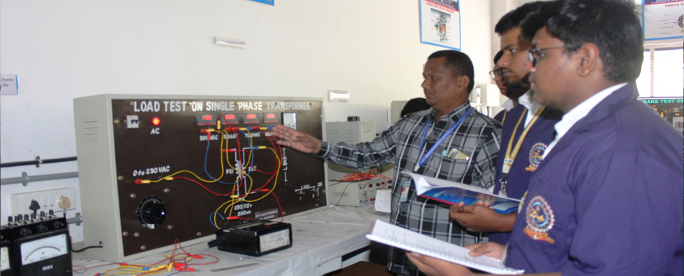
| 31 | LOAD TEST ON SINGLE PHASE TRANSFORMER |
| 32 | THREE PHASE TRANSFORMER |
| 33 | ACTIVE/ REACTIVE POWER IN THREE PHASE CIRCUIT |
ELECTRICAL MACHINES LAB.-I & II
This lab is equipped with AC and DC machines. The objective of this laboratory is to learn about determination of input power, out power and efficiency. The experiments includes load test, brake test, Hopkinson’s test, Fields test ,Swinburne’s test on motors and generators and also includes determination of magnetization characteristics of DC shunt generator. This laboratory course will help the students to understand the theoretical concepts. It can accommodate 36 students perform 12 experiments simultaneously. Provided with generator back up and it has qualified technicians for conducting experiments and for regular maintenance of the labs
LIST OF EQUIPMENT
| S.No | DESCRIPTION OF THE EQUIPMENT WITH SPECIFICATIONS & RANGES |
| 1 | DC Motor–Generator set (SHUNT/SHUNT) DC SHUNT MOTOR 5HP, 220V,1500RPM COUPLED ON CHANNEL FRAME TO DC SHUNT GENERATOR 220V, 3KW, 1500RPM (WITH 3 POINT STARTER) |
| 2 | DC Motor–Generator set (SHUNT/SHUNT) TWO IDENTICAL DC SHUNT MACHINES 5HP,220V,1500RPM COUPLED ON CHANNEL FRAME (WITH 3 POINT STARTER) |
| 3 | DC Motor–Generator set (SHUNT/SERIES) DC SHUNT MOTOR 5HP, 220V,1500RPM COUPLED ON CHANNEL FRAME TO DC SERIES GENERATOR 220V, 3KW, 1500RPM (WITH 3 POINT STARTER) |
| 4 | DC Motor–Generator set (SHUNT/COMPOUND) DC SHUNT MOTOR 5HP, 220V,1500RPM COUPLED ON CHANNEL FRAME TO DC COMPOUND GENERATOR 220V, 3KW, 1500RPM (WITH 3 POINT STARTER) |
| 5 | DC MOTOR–GENERATOR SET ( SERIES/ SERIES) DC SERIES MACHINES. 3 KW / 220 V / 1500 RPM / DC SERIES IDENTICAL MACHINES COUPLED WITH EACH OTHER WITH BASE AND COUPLING. (WITH 2 POINT STARTER) FOR FIELD’S TEST ON DC SERIES MACHINES. |
| 6 | DC SHUNT MOTOR 5HP, 220V,1500RPM WITH MECHANICAL LOADING ARRANGEMENT AND WITH 3 POINT STARTER |
| 7 | DC SHUNT MOTOR 5HP, 220V,1500RPM WITH BASE PLATE AND WITH 3 POINT STARTER |
| 8 | DC COMPOUND MOTOR 5HP, 220V,1500RPM WITH MECHANICAL LOADING ARRANGEMENT AND WITH 4 POINT STARTER |
| 9 | CUT TRANSPARENT WORKING MODEL WITH ALL PARTS LIKE FIELD WINDING, INTERPOLES, ARMATURE, COMMUTATOR, FAN ROCKER AND CARBON BRUCH HOLDER ASSEMBLY VISIBLE. |
| 10 | RECTIFIER UNIT AC INPUT 3-PHASE,440V,DC OUTPUT 220V, 100A,WITH BOOST AND BUCK PRESS BUTTONS. |
| 11 | TRANSFORMER SINGLE-PHASE TRANSFORMER 3KVA, 220/110V, 50Hz, WITH TAPPINGS |
| 12 | TRANSFORMER SINGLE-PHASE TRANSFORMER 3KVA, 220/115V, 50Hz, WITH TAPPINGS |
| 13 | TRANSFORMER SINGLE-PHASE TRANSFORMER 1KVA, 220/220V, 50Hz, WITH TAPPINGS |
| 14 | TRANSFORMER SINGLE-PHASE TRANSFORMER 3KVA, 220/220V, 50Hz, WITH TAPPINGS |
| 15 | SNGLE PHASE AUTO-TRANSFORMER SINGLE-PHASE AUTO-TRANSFORMER 230/0-260V, 15A, 50Hz |
| 16 | AUTO-TRANSFORMER SINGLE-PHASE AUTO-TRANSFORMER 230/0-260V, 15A, 50Hz |
| 17 | AUTO-TRANSFORMER THREE PHASE AUTO-TRANSFORMER 415/0-460V, 15A, 50Hz |
| 18 | BOOSTER-TRANSFORMER SINGLE-PHASE BOOSTER TRANSFORMER 1.5KVA 230/0-60V, 30A, 50Hz |
| 19 | THREE-PHASE,SQUIRREL CAGE INDUCTION MOTOR 3.7KW, 415V, 50Hz 1430RPM 7.5Amps WITH MECHANICAL LOADING ARRANGEMENT AND WITH STAR\DELTA STARTER |
| 20 | THREE-PHASE,SLIP RING INDUCTION MOTOR 5HP, 415V, 50Hz 930RPM,14.7 Amps WITH MECHANICAL LOADING ARRANGEMENT AND WITH ROTOR RESISTANCE STARTER ROTOR 110V, |
| 21 | THREE-PHASE,SQUIRREL CAGE INDUCTION MOTOR 5HP, 415V, 50Hz 1500RPM WITH MECHANICAL LOADING ARRANGEMENT AND WITH STAR\DELTA STARTER |
| 22 | SINGLE-PHASE,INDUCTION MOTOR CAPACITOR START CAPACITOR RUN 2HP 220V, 7.6Amps 50Hz 1425 RPM WITH MECHANICAL LOADING ARRANGEMENT AND WITH D.O.L. STARTER |
| 23 | MOTOR - ALTERNATOR SET DC SHUNT MOTOR 5HP, 220V, 1500RPM, COUPLED ON CHANNEL FRAME TO THREE -PHASE ALTERNATOR 3KVA, 440V, (WITH THREE POINT STARTER) |
| 24 | MOTOR - ALTERNATOR SET DC SHUNT MOTOR 5HP, 220V, 1500RPM, COUPLED ON CHANNEL FRAME TO THREE -PHASE SALIENT POLE ALTERNATOR 5KVA, 440V, (WITH THREE POINT STARTER) |
| 25 | SYNCHRONOUS MOTOR SYNCHRONOUS MOTOR 5HP, 415V, 3-PHASE, WITH 0.75KW DC GENERATOR FOR EXITATION WITH BRAKE LOAD PULLEY BELT LOAD CHANGING ARRANGEMENT DIAL TYPE SPRING BALANCES |
| 26 | RHEOSTATS 350ohms,/2Amps |
| 27 | RHEOSTATS 50ohms,/5Amps |
| 28 | RHEOSTATS 290ohms,/2.8Amps |
| 29 | RHEOSTATS 560ohms,/1.2Amps |
| 30 | RHEOSTATS 1500ohms,/1.2Amps |
| 31 | RHEOSTATS 12ohms,/12Amps |
| 32 | RHEOSTATS 100ohms,/5Amps |
| 33 | RESISTIVE LOAD SINGLE PHASE 230V, 20A,WITH 10 STEPS OF 2A. |
| 34 | RESISTIVE LOAD SINGLE PHASE 230V, 10A,WITH 10 STEPS OF 1A. |
| 35 | RESISTIVE LOAD SINGLE PHASE 6KW, 230V WITH STEPS |
| 36 | THREE-PHASE RESISTIVE LOAD SINGLE PHASE 12KW, 415V WITH STEPS |
| 37 | TACHOMETER DIGITAL HANDHELD TACHOMETER (0-9999)RPM |
| 38 | TACHOMETER DIGITAL NON CONTACT TYPE DIGITAL HANDHELD TACHOMETER (0-9999)RPM |
| 39 | AMMETER MI (0-1/2)A |
| 40 | AMMETER MI (0-10/20)A |
| 41 | AMMETER MI (0-15/30)A |
| 42 | AMMETER MC (0-1/2)A |
| 43 | AMMETER MC (0-10/20)A |
| 44 | AMMETER MC (0-15/30)A |
| 45 | VOLTMETER MI (0-250/500)V |
| 46 | VOLTMETER MI (0-150/300)V |
| 47 | VOLTMETER MI (0-75/150)V |
| 48 | VOLTMETER MC (0-150/300)V |
| 49 | VOLTMETER MC (0-25/50)V |
| 50 | AMMETER MC (0-1/2)A |
| 51 | AMMETER MC (0-10/20)A |
| 52 | AMMETER MC (0-30)A |
| 53 | AMMETER MI (0-1/2)A |
| 54 | AMMETER MI (0-10/20)A |
| 55 | AMMETER MI (0-15/30)A |
| 56 | AMMETER MI (0-1/2)A |
| 57 | AMMETER MI (0-1/2)A |
| 58 | AMMETER MI (0-10/20)A |
| 59 | AMMETER MI (0-15/30)A |
| 60 | VOLTMETER MI (0-300/600)V |
| 61 | VOLTMETER MI (0-150/300)V |
| 62 | VOLTMETER MI (0-75/150)V |
| 62 | VOLTMETER MI (0-30/60)V |
| 64 | VOLTMETER MI (0-300/600)V |
| 65 | VOLTMETER MC (0-150/300/600)V |
| 66 | WATTMETER UPF 75/150/300V, 5/10A |
| 67 | WATTMETER UPF 300/600V, 10/20A |
| 68 | WATTMETER UPF 50/100V, 10/20A |
| 69 | WATTMETER UPF 75/150V, 10/20A |
| 70 | WATTMETER UPF 300/600V, 10/20A |
| 71 | 3 PHASE WATTMETER UPF 150/300/600V, 15/30A |
| 72 | WATTMETER LPF 150/300V, 1/2A |
| 73 | WATTMETER LPF 300/600V, 1/2A |
| 74 | WATTMETER LPF 75/150V, 1/2A |
| 75 | WATTMETER LPF 300/600V, 5/10A |
| 76 | WATTMETER LPF 75/150/300V, 2.5/10A |
| 77 | WATTMETER UPF 150/300/600V, 10/20A |
| 78 | 3 PHASE VARIABLE INDUCTIVE LOAD ,10 A,440V |
| 79 | DPST KNIFE SWITCH |
| 80 | TPST KNIFE SWITCH |
| 81 | FOUR COIL WINDER MACHINE MANUAL TYPE |
| 82 | RUBBER MAT |
| 83 | POWER FACTOR METER,1 PHASE, (150/300/600)V,10/20 A |
| 84 | 2 POINT STARTER(FOR DC SERIES MOTOR) |
| 85 | DIGITAL MULTIMETER |
ELECTRICAL MEASUREMENT LAB
The objective of Electrical Measurements laboratory is to determine the measurement of Capacitance and Inductance values. This laboratory course will help the students to understand the theoretical concepts. This lab is also equipped with Energy Meter, Dynamometer Power Factor Meter, D.C. Potentiometer, Kelvin’s Double Bridge, Schering Bridge & Anderson Bridge, LVDT and Choke Coil .It can accommodate 36 students perform 10 experiments simultaneously.
LIST OF EQUIPMENT
| S.No | DESCRIPTION OF THE EQUIPMENT |
| 1 | CALIBRATION OF SINGLE PHASE ENERGY METER |
| 2 | CALIBRATION OF DYNAMOMETER TYPE “POWER FACTOR METER” |
| 3 | KELVIN’S DOUBLE BRIDGE |
| 4 | CROMPTON DC POTENTIOMETER KIT |
| 5 | SCHERING BRIDGE AND ANDERSON BRIDGE |
| 6 | C.T.TESTING BY SILSBEE METHOD |
| 7 | MEASUREMENT OF POWER BY 3-AMMETER AND 3-VOLTMETER METHOD |
| 8 | LVDT MEASUREMENT KIT |
| 9 | CALIBRATION OF SINGLE PHASE WATT-METER BY PHANTOM LOADING |
| 10 | MEASUREMENT OF 3 PHASE REACTIVE POWER WITH SINGLE PHASE METER |
| 11 | MEASUREMENT OF THREE PHASE POWER WITH SINGLE WATT-METER & 2 NOS OF CT |
| 12 | RESISTANCE STRAIN GUAGE MEASUREMENT KIT |
| 13 | C.T TESTING USING MUTUAL INDUCTOR KIT |
| 14 | P.T TESTING BY COMPARISON AS NULL DETECTOR METHOD KIT |
| 15 | TRANSFORMER TURNS RATIO MEASUREMENT KIT(NULL TYPE METHOD) |
| 16 | DI-ELECTRIC OIL TESTING USING H.T TESTING KIT |
ELECTRICAL SYSTEMS SIMULATIONS LAB
COMPUTER FACILITIES:
| S.NO | DESCRIPTION |
| 1. | P-IV Computer Systems With 512MB RAM, 80 GB Hard Disc, TFT 15 Color Monitor & Multimedia Keyboard. |
LIST OF SOFTWARES:
| S.NO | DESCRIPTION OF SOFTWARES |
| 1. | OrCAD Simulation Suite consists of Capture CIS Option, Pspice A/ D, Pspice Advanced Analysis & Pspice SLPS Option- |
| 2. | MATLAB |
| 3. | SIMULINK |
| 4. | Control System Toolbox |
| 5. | Simpower Systems (Prerequisite Simulink) |
| 6. | Simulink Control Design (Prerequisite Simulink Control System Toolbox) |
ELECTRICAL WORKSHOP LAB
LIST OF EQUIPMENTS
| S.NO | DESCRIPTION OF THE EQUIPMENT WITH SPECIFICATIONS & RANGES |
| 1 | Design and fabrication of reactor/ electromagnet for different inductance values. |
| 2 | Design and fabrication of single phase Induction/three phase motor stator. |
| 3 | Start delta starter wiring for automatic and manual operation. |
| 4 | Wiring of distribution box with MCB, ELCB, RCCB and MCCB |
| 5 | Wiring of 40 W tube, T-5, LED, Metal Halide lamps and available latest luminaries. |
| 6 | Assembly of various types of contactors with wiring |
| 7 | Assembly of DOL and 3 point starter with NVC connections and overload operation. |
| 8 | Design and development of 5 V regulated power supply |
| 9 | Design and development of precision rectifier. |
| 10 | Design and development of first order/ second order low pass/high pass filters with an application |
| 11 | Microcontroller Interface circuit for temperature/level/speed/current/voltage measurement. |
| 12 | Peak detector using op-amplifiers. |
| 13 | Zero crossing detector using op-amplifiers |
POWER ELECTRONICS LAB
The objective of Power Electronics and simulation laboratory is to analyses the Gate Firing Circuits for SCRs ,choppers. The student will understand the characteristics of power electronic devices with gate firing circuits, Various forced commutation techniques, The operation of single-phase voltage controller, converters and Inverters circuits with R and RL loads, Analyze the TPS7A4901, TPS7A8300 and TPS54160 buck regulators. This lab is equipped with Gate Firing Circuits ,AC Voltage Controller , Bridge Converter , Forced Commutation Circuits , DC Jones Chopper , Series Inverter , Dual Converter and it can accommodate 36 students perform 10 experiments simultaneously.
LIST OF EQUIPMENT
| S.NO | DESCRIPTION OF THE EQUIPMENT |
| 1 | STATIC CHARACTERISTICS of SCR, TRAIC, DIAC, MOSFET, AND IGBT KIT METERS UNIT :METERS UNIT CONSIST OF a) DC AMMETER (0-500) mA & (0-25)mA and b)DC VOLTMETER (0-50)V & (0-15)V |
| 2 | GATE FIRING CIRCUITS UNITS a)BASIC DC FIRING CIRCUIT |
| 3 | SINGLE PHASE AC VOLTAGE CONTROLLER UNIT WITH IN-BUILT FIRING PULSES TO TRIGGER ACCESSORIES: a)RHEOSTAT – 50 Ω/ 2A -1NO b)INDUCTOR 150 MH/5A - 1NO. WITH TAPINGS |
| 4 | SINGLE PHASE FULLY CONTROLLED (BRIDGE) CONVERTER POWER CIRCUIT ACCESSORIES: |
| 5 | FORCED COMMUTATIONS STUDY UNIT- FCU ACCESSORIES: a)RHEOSTAT – 150 Ω/ 5A -1no |
| 6 | DC - CHOPPER (JONES )POWER CIRCUIT – SDCP ACCESSORIES: a)DC CHOPPER TRIGGERING UNIT |
| 7 | PARALLEL & SERIES INVERTER –UNITS WITH IN-BUILT TRIGGERING UNIT ACCESSORIES: |
| 8 | SINGLE PHASE CYCLO CONVERTER POWER CIRCUIT - SCYP a)SINGLE PHASE CYCLO CONVERTER TRIGGERING UNIT |
| 9 | SINGLE PHASE HALF CONTROLLED CONVERTER POWER CIRCUIT ACCESSORIES: a)SINGLE PHASE TRIGGERING UNIT |
| 10 | SINGLE PHASE DUAL CONVERTER POWER CIRCUIT – SDP ACCESSORIES: a)SINGLE PHASE DUAL CONVERTER FIRING UNIT |
| 11 | DIGITAL STORAGE OSCILLOSCOPE DSO-25C1 – 25MHZ |
| 12 | DUAL TRACE OSCILLOSCOPES OSO2O- 20 MHz |
| 13 | DIGITAL MULTIMETER DMM – 10- 3 ¾ DIGIT DISPLAY |
| 14 | L C R METER LCR010P |
| 15 | BUCK AND BOOST CHOPPER KIT |
| 16 | THREE PHASE HALF CONTROLLED RECTIFIER KIT |
POWER SYSTEMS LAB
The objectives of this Power Systems & Simulation Laboratory includes determination (in machines lab) of sequence impedance and sub-transient reactance’s of synchronous machine, analyzing of LG, LL, LLG, LLLG faults,
LIST OF EQUIPMENTS
| S.NO. | DESCRIPTION OF THE EQUIPMENT WITH SPECIFICATIONS & RANGES |
| 1 | Characteristics of IDMT Over Current Relays. The following equipments are fitted on panel with terminals:- |
| 2 | Differential protection single phase transformer The following equipments are fitted on panel with terminals:- (1)Single Phase Differential Relay (2)Digital ammeters. (3)Control and protection circuit duly wired. (4)Phantom Fault with continuously variable auto transformers and current limiter. (5)Auxiliary supply. (6)Alarm. |
| 3 | Microprocessor Based Over Voltage and Under Voltage Relay The following equipments are fitted on panel with terminals:- |
| 4 | Testing of (1)CT’s (2)PT’s (3)Insulator StringsThe following equipments are fitted on control panel with terminals:- Voltmeter for primary and secondary (1)3 Ammeters each for primary and secondary |
| 5 | Determination of Sequence Impedances of a Synchronous machines. Equipments: - For DC motor1. DC starter with no volt and over load protection For Synchronous generator1. M.I Voltmeter 96x96mm 0-150V |
| 6 | Finding the Sequence Impedance of Three Phase Transformer. Equipment Installed: Objective type terminals for all the items will be provided on the panel for performing experiments on various Parameters Price of complete setup with control panel. |
| 7 | LG, LL and 3 phase fault Analysis of 3 phase Synchronous Machine Complete experimental set up to study the 1.Line to line fault 2.3-phase fault Equipment Required: - It will comprise of DC Shunt motor 5HP, 220V, directly coupled to synchronous generator 3KVA on common channel base frame. Machine will conform to ISS 4722. “TECH TRACK MAKE an ISO 9001-2015Manufacturing Co.”</strong CONTROL PANEL It consist of nicely powder coated M.S. fabricated box with screen printed circuit will be fitted on the panel with duly marked termination and also back door of the panel will have lock facility for safety of panel. All the necessary accessories such as:- For DC motor1. DC starter with no volt and over load protection For Synchronous generator1. M.I Voltmeter 96x96mm 0-150V |
| 8 | power circle diagrams of a 3 – Φ Transmission Line Model. Transmission line model is on line operatable at 420V with current rating at 5A connected in n network. A continues variable power supply with two Digital Voltmeter and two digital ammeter, Resistive Load mounted on front panel with resistive, inductive, capacitive load fitted in M.S. Box “TECH TRACK MAKE an ISO 9001-2015Manufacturing Co.” NB: - Complete illustrated manual covering brief theory of equipments along with technical details and experimental procedures, Connection diagrams will be supplied with above experimental set up |
| 9 | ABCD constants and regulation of 3 phase Transmission line model Transmission line model is on line operatable at 420V with current rating at 5A connected in n network. A continues variable power supply with two Digital Voltmeter and two digital ammeter, Resistive Load mounted on front panel with resistive, capacitive load fitted in M.S. Box NB: - Complete illustrated manual covering brief theory of equipments along with technical details and experimental procedures, Connection diagrams will be supplied with above experimental set up |
| 10 | Three Phase Auto Transformer |
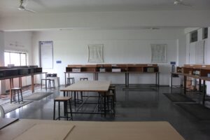
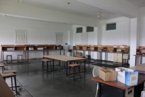
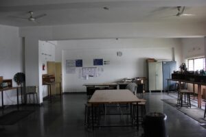
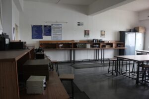
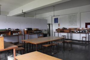
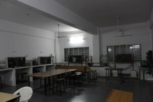
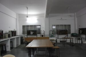
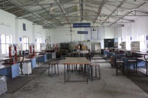
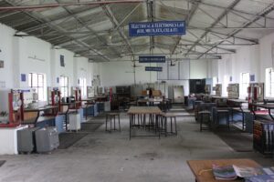
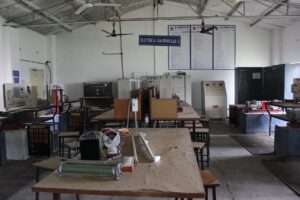
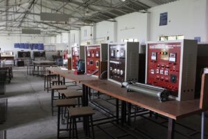
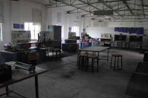
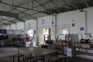
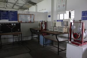
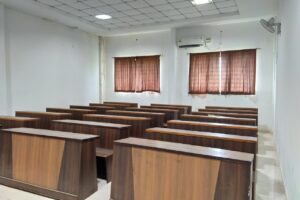
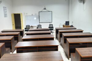
The following are the photos of the labs in the department
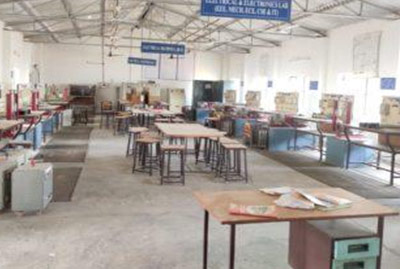
ELECTRICAL MACHINES-I&II LAB

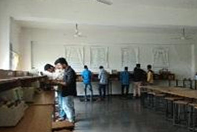
ELECTRICAL MEASUREMENTS LAB

CONTROL SYSTEM LAB
POWER ELECTRONICS LAB
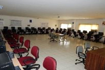
Simulation Lab
R & D LAB